

Compensating for Runout in Engraving Tools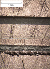
by Joerg Hugel
With CNC mills, engraving letters and figures in a workpiece is a simple task. But, it must be regarded that engraving cutters are very delicate tools, especially if very fine lines shall be produced. I’ve observed that, when engraving printed circuit boards with the same style cutter, sometimes the lines came out clean and clear as desired and on other occasions the lines had rough and frazzled edges. Both results are seen in Photo 1.
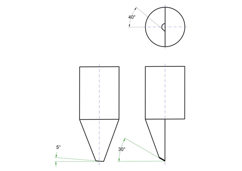
PCB material with a thin, copper layer is a very suitable material to check engraving cutters – any bad cutting action is sensitively felt with a finger’s tip. My usual engraving cutter is made from tungsten carbide and its geometry is seen in the drawing.
The reason most often responsible for the different results is the runout of the tool’s tip. Those tiny cutters must run exactly concentric and this is not always guaranteed. The fast-running Proxxon grinder I use for engraving has .05mm runout, and this is too much if the cutting edge is n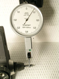 ot located in the area of greatest runout. Now, I generally use a DTI as seen in Photo 2 for setting engraving cutters in the spindle’s collets; the cutting edge and the maximum runout simply must be in the same location. Otherwise, the flank behind the cutting edge can foul the workpiece, with the result that the edges of the engraved lines become “frazzled.” Of course, the runout will increase the line width. For example, .1 mm for .05 mm runout.
Thanks Joerg, your subscription has been extended by an issue!
Please do us a tremendous favor and forward this e-mail to your machining friends!
|
||
 
|
 
|
 
|
{UNSUBSCRIBEHYPERLINK} {OPENEDEMAILMARKER}